
Functional Assembly Fit and Clearance Validation Kit
- Precision Machining Tolerance Verification Guide
- Injection Molding Design for Manufacturability Checklist
- Additive Manufacturing Structural Integrity Assessment
- Material Selection and Durability Evaluation Protocol
- Prototype-to-Production Transition Readiness Manual
- Functional Assembly Fit and Clearance Validation Kit
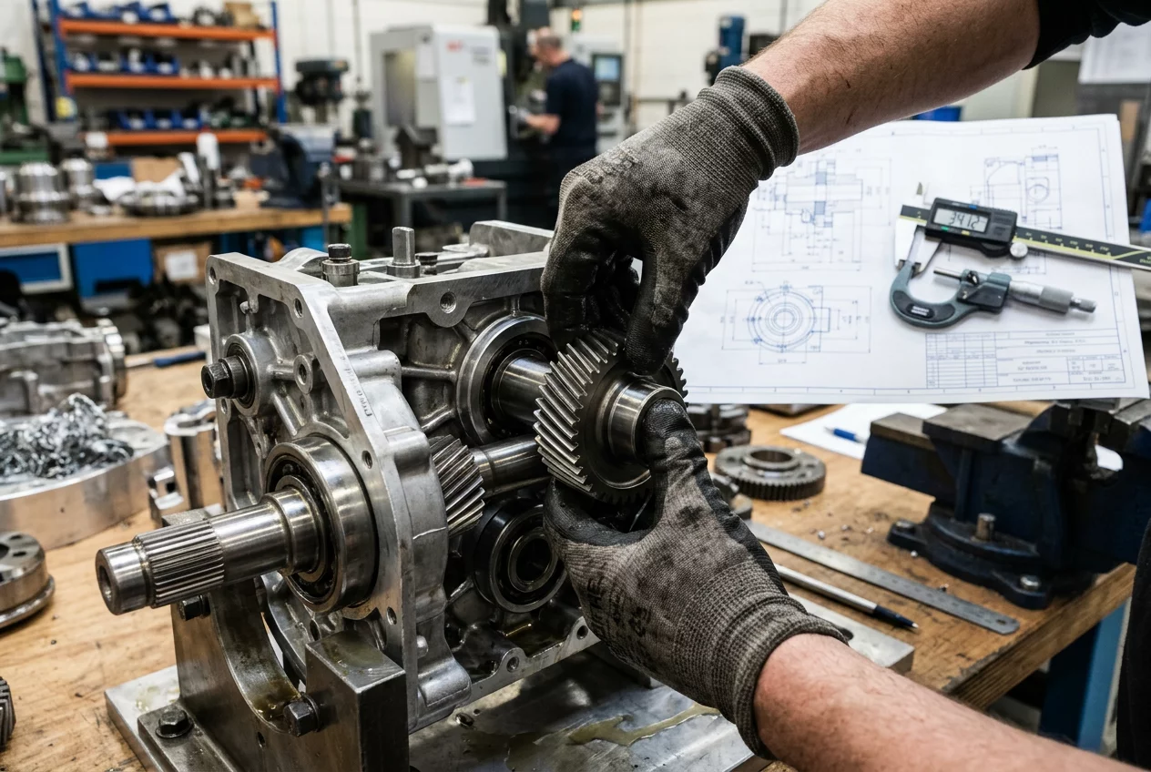
Functional Assembly Fit and Clearance Validation Kit
Ensuring Seamless Interaction Between Components
A mechanical system is only as good as the fit between its constituent parts. When multiple components are assembled, the individual tolerances of each part interact in complex ways, a phenomenon known as tolerance stack-up. If these interactions are not managed, the resulting assembly may be too tight to move, too loose to function, or impossible to put together at all. This validation kit provides the tools and methodologies for analyzing fits and clearances, ensuring that your functional assembly operates exactly as intended from the very first unit off the line.
Analyzing Fit Types and Engineering Standards
The relationship between two mating parts is categorized into three primary types: clearance, transition, and interference fits. A clearance fit ensures there is always a gap, allowing for free movement or easy assembly. An interference fit, or 'press fit,' requires force to join the parts, creating a permanent or semi-permanent bond. Transition fits fall in between, used for precise location where a slight clearance or interference might occur. Using established standards like ISO or ANSI for these fits provides a reliable baseline, but the PartPass Field Guide suggests validating these choices through physical 'fit checks' using 3D-printed or machined master gauges.
Mastering Tolerance Stack-Up Analysis
Tolerance stack-up is the cumulative effect of individual part tolerances on a final assembly dimension. For example, if five plates are stacked, and each has a tolerance of +/- 0.1mm, the total height of the stack could vary by +/- 0.5mm. This variation can lead to interference with a housing or a failure of a fastener to reach its threads. Validation involves performing Worst-Case Analysis (WCA) or Root Sum Squared (RSS) statistical analysis to predict these variations. By identifying which dimensions contribute most to the stack-up, engineers can tighten tolerances where they matter most while loosening them elsewhere to save costs.
Validation Through Functional Gauging
While digital measurements are essential, functional gauging provides a 'real-world' check of assembly readiness. A functional gauge is a custom tool designed to simulate the mating part or the assembly environment. For instance, a 'Go/No-Go' gauge can quickly verify if a shaft is within the size limits to fit into its corresponding hole. These tools are particularly valuable on the production line, as they allow operators to verify complex geometric conditions—like the position of a bolt pattern—much faster than a CMM. The validation kit includes instructions for designing these gauges to match the specific needs of your assembly.
Evaluating Clearance for Thermal and Dynamic Loads
Static fit is only one part of the story. Components in motion or those subject to temperature changes require dynamic clearance. As parts heat up, they expand; if the initial clearance is too small, the assembly may seize. Similarly, moving parts need space for lubricants and must account for the slight deflections that occur under load. The validation process includes 'hot and cold' testing and high-speed cycles to observe how clearances change during operation. Ensuring that there is sufficient 'breathing room' for these real-world variables prevents premature wear and ensures the long-term reliability of the functional assembly.